One project, two phases
Phase 2 · Three-person team
Custom Pivot Rig
Reusing my first drone’s hardware to work toward a self-landing system.
I brought in two teammates for this phase. We designed our own frame and built a constrained pivot rig, using the electronics and propulsion hardware I already had.
Explore the engineering ↓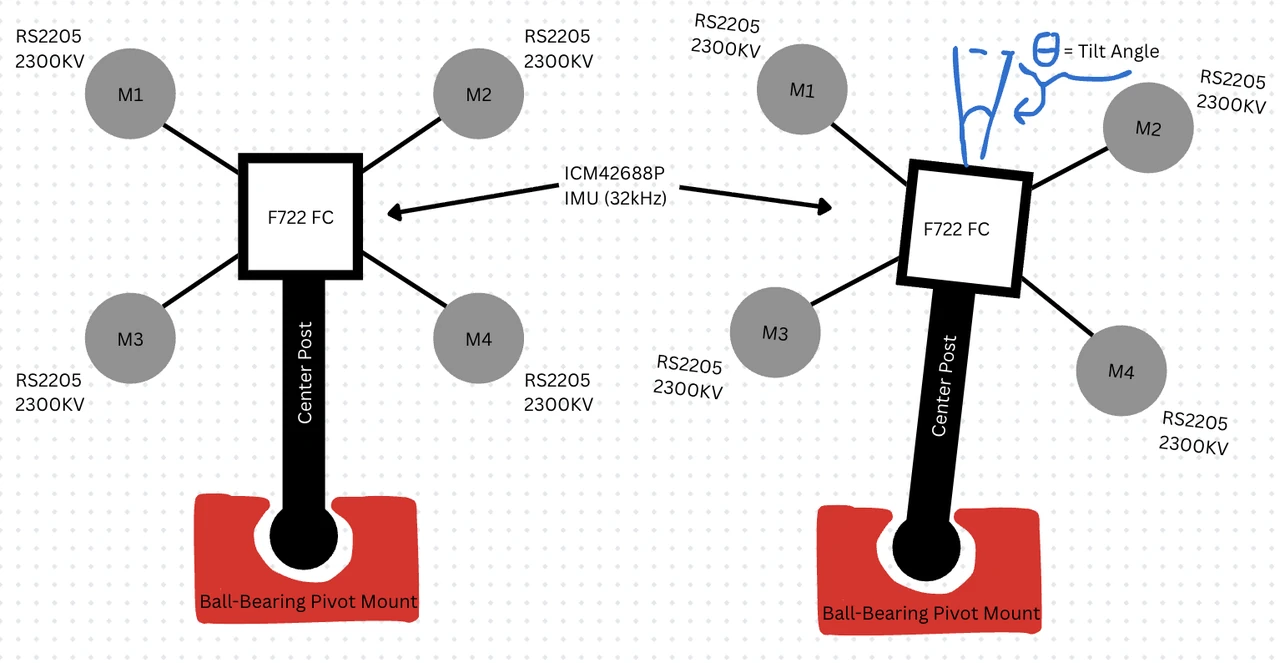
- My role
- Hardware assembly · model explorer & mission-control tools
- Status
- Bench validation; integrated landing not demonstrated
- Team / new materials
- 3 members · $21.99 PLA spool
Result & scope
The final report records a 3.16× reduction in spin-down time with active counter-torque. Attitude settling remained outside the report’s error target.
- 01
Model
Separate descent, motor spin-up, rotation, attitude, and guidance.
- 02
Build
Assemble the quad-rotor module and instrument a constrained pivot rig.
- 03
Compare
Compare predicted response with the reported bench measurements.
- 04
Revise
Update parameters and carry unvalidated behavior into the next test.
Inside Phase 2
Inside the work.
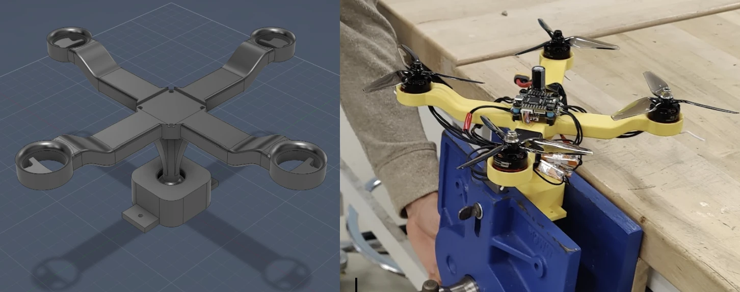
Team-designed X-frame beside the assembled bench rig. The fixture enables controlled rotational tests.
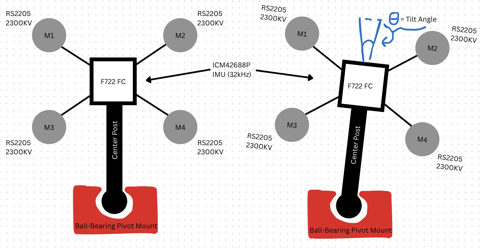
The pivot constrains translation. This setup tests rotation; it cannot demonstrate landing accuracy.
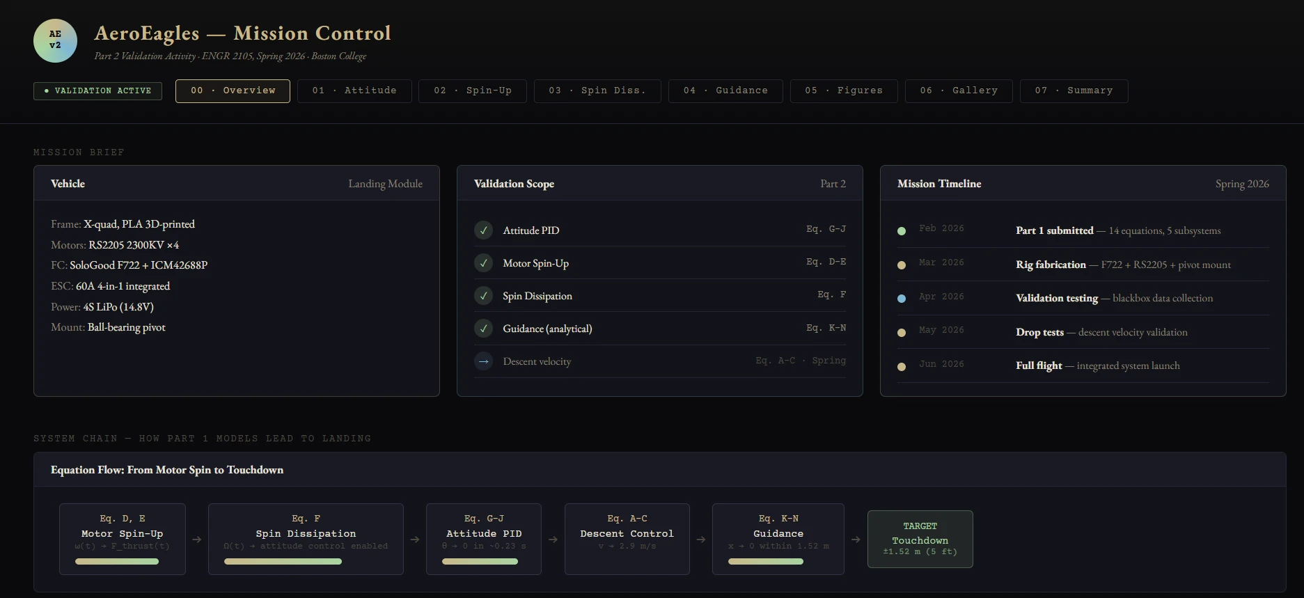
The project’s comparison tool connects model parameters to reported validation results.
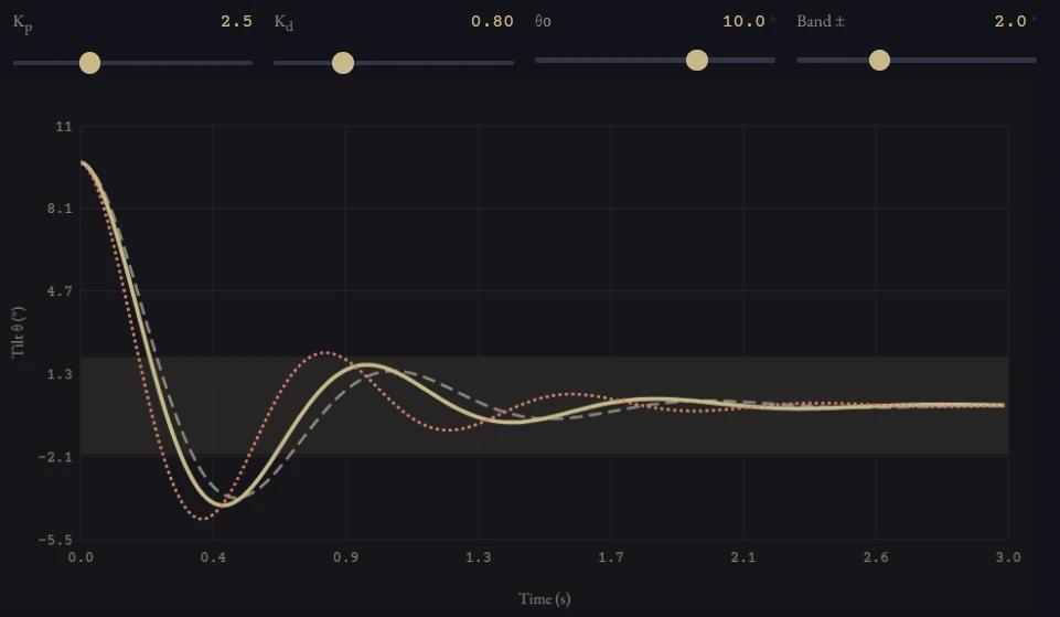
Reported PID comparison. Settling time misses the 15% error criterion.
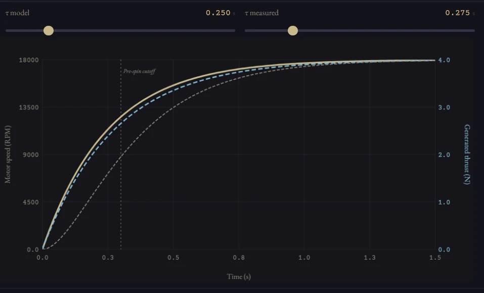
Reported first-order response: 0.25 s predicted versus 0.28 s measured time constant.
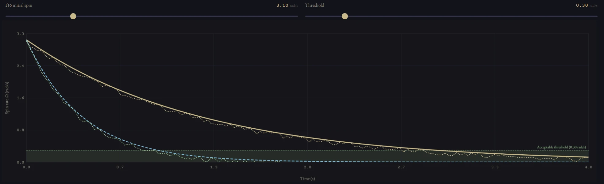
Reported reduction from 3.10 s to 0.98 s, approximately 3.16×.
| Metric | Prediction | Reported measurement |
|---|---|---|
| Motor time constant | 0.25 s | 0.28 s |
| Passive spin-down | 2.87 s | 3.10 s |
| Active spin-down | 0.92 s | 0.98 s |
| Attitude settling | 0.23 s | 0.29 s — outside target |
My contribution and the team
I led overall hardware assembly of the landing module and developed the AeroEagles Model Explorer and Mission Control web tools used for prediction figures and validation comparisons. I also worked on machine-learning integration planning; that is a planned extension, not a demonstrated learned controller.
My teammates handled CAD/printing of the four rig iterations, OpenRocket modeling, Betaflight configuration, radio integration, and blackbox export. Our final report breaks down our contributions and the validation results.
Why a pivot rig?
The quad-pivot rig made attitude response and spin behavior observable while constraining translation. The report describes RS2205 2300 KV motors, an F722 controller, an ICM42688P IMU, and 2 kHz blackbox telemetry.
The constraint is also a limitation: a bench vise introduces friction, and the rig cannot validate horizontal translation or the full descent sequence. A ball-bearing pivot is a documented improvement for a future rig.
What the comparison showed
The report gives motor spin-up time constants of 0.25 s predicted and 0.28 s measured. Passive spin-down took 3.10 s; active counter-torque took 0.98 s. Attitude settling was 0.29 s against a 0.23 s prediction, a 26.1% discrepancy.
The report attributes attitude discrepancies to fixture friction and gain scaling. Those explanations motivate follow-up tests; they are not proof that the discrepancy disappears in flight.
What remains open
Horizontal correction is an analytical re-calibration, not a measured free-flight landing. Descent velocity and the integrated landing sequence were deferred in the May 2026 report. Self-landing is still the goal; the work shown here is the bench-tested step toward it.
Read the source
Technical records.
Report notes
AeroEagles final report, May 7, 2026: group contributions and validation sections; Part 1 and Part 2 reports. Values are reported results, not a new independent re-analysis of raw telemetry.
Phase 2 / Reuse before buying
A new platform. $21.99 in new material.
We fabricated the custom components in-house with makerspace tools and reused the existing propulsion and electronics stack. The only new material purchase was a 1 kg spool of PLA. The frame used a fraction of that spool; the cost below counts the whole purchase.
| Item | Source | Additional purchase |
|---|---|---|
| Brushless motors and ESCs | Reused from Phase 1 | $0 |
| Flight controller / IMU | Reused from Phase 1 | $0 |
| LiPo battery and propellers | Reused from Phase 1 | $0 |
| Wiring and connectors | Reused from Phase 1 | $0 |
| Fasteners and miscellaneous hardware | Makerspace stock | $0 |
| 3D printer and soldering equipment | Makerspace equipment | $0 |
| Hand tools and test equipment | Makerspace equipment | $0 |
| PLA filament · 1 kg spool | New purchase | $21.99 |
| Phase 2 new material cost | $21.99 | |
$0 means no additional purchase for this phase. Reused hardware and makerspace equipment still have value.
Phase 1 · Individual build
Learn the hardware.
Before making my own drone, I wanted to understand one from the inside out.
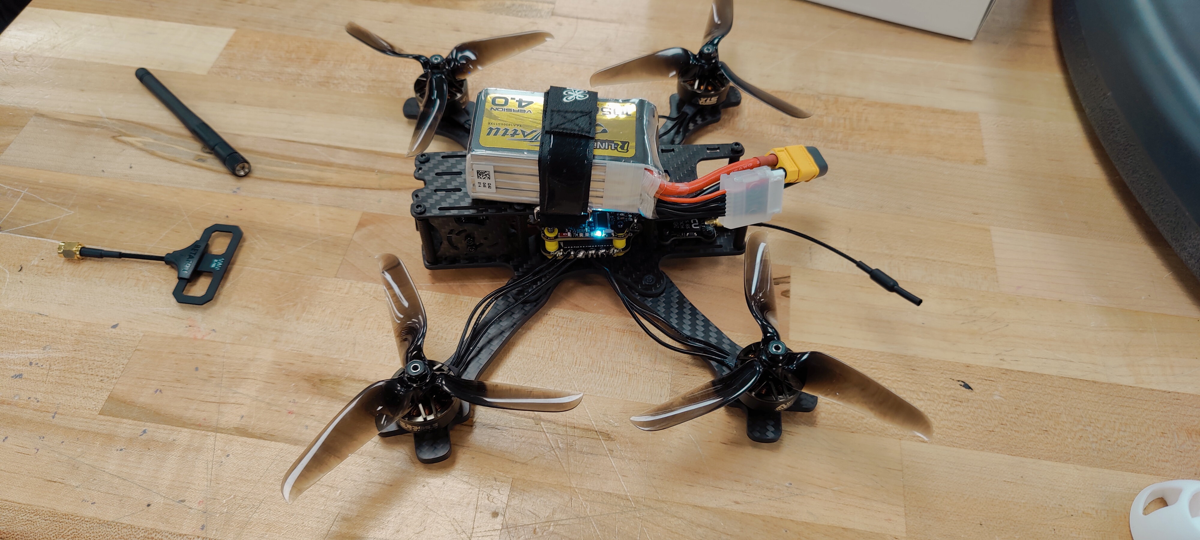
I ordered a kit and assembled and configured the quadcopter myself. This was my starting point for learning the hardware stack, getting used to simulation and Betaflight, and learning to build and fly. It was also just fun.
- Team
- Individual build
- Purchased materials
- $239.32
- Purpose
- Assembly, configuration, and drone familiarization
From parts to a working hardware stack
The first build.
The assembled kit quadcopter on the workbench, with its battery, electronics, and propellers installed.
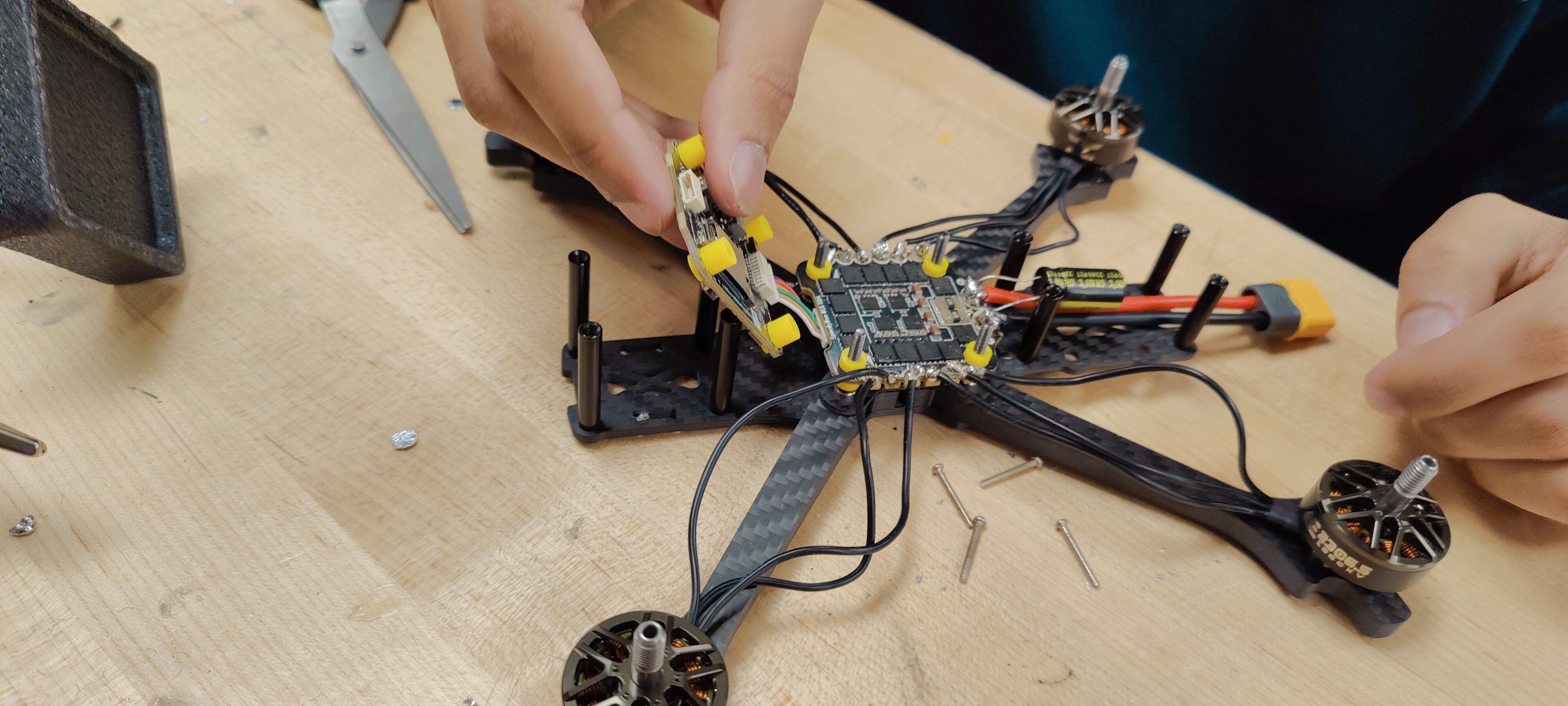
Installing the flight-controller stack above the propulsion electronics and motor wiring.
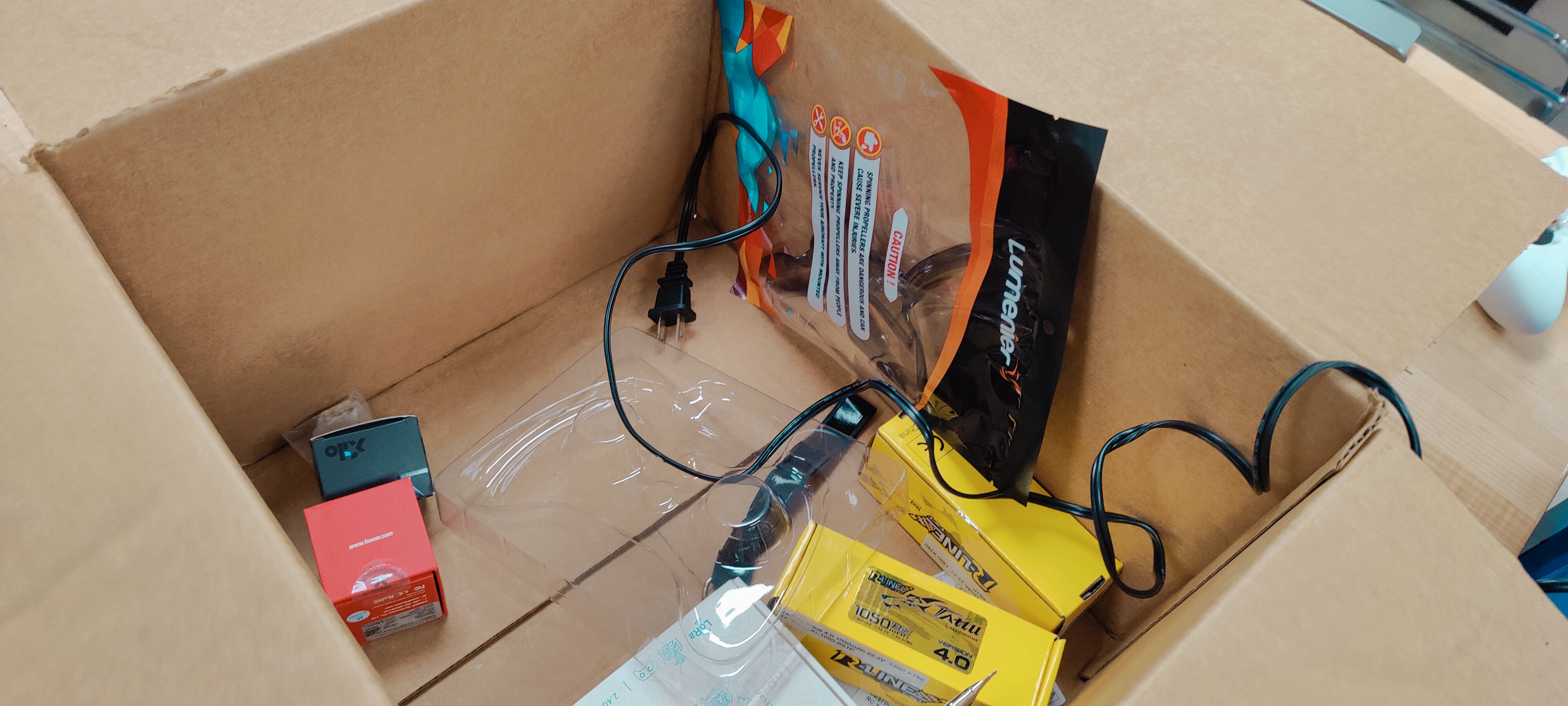
The kit hardware and accessories before assembly.
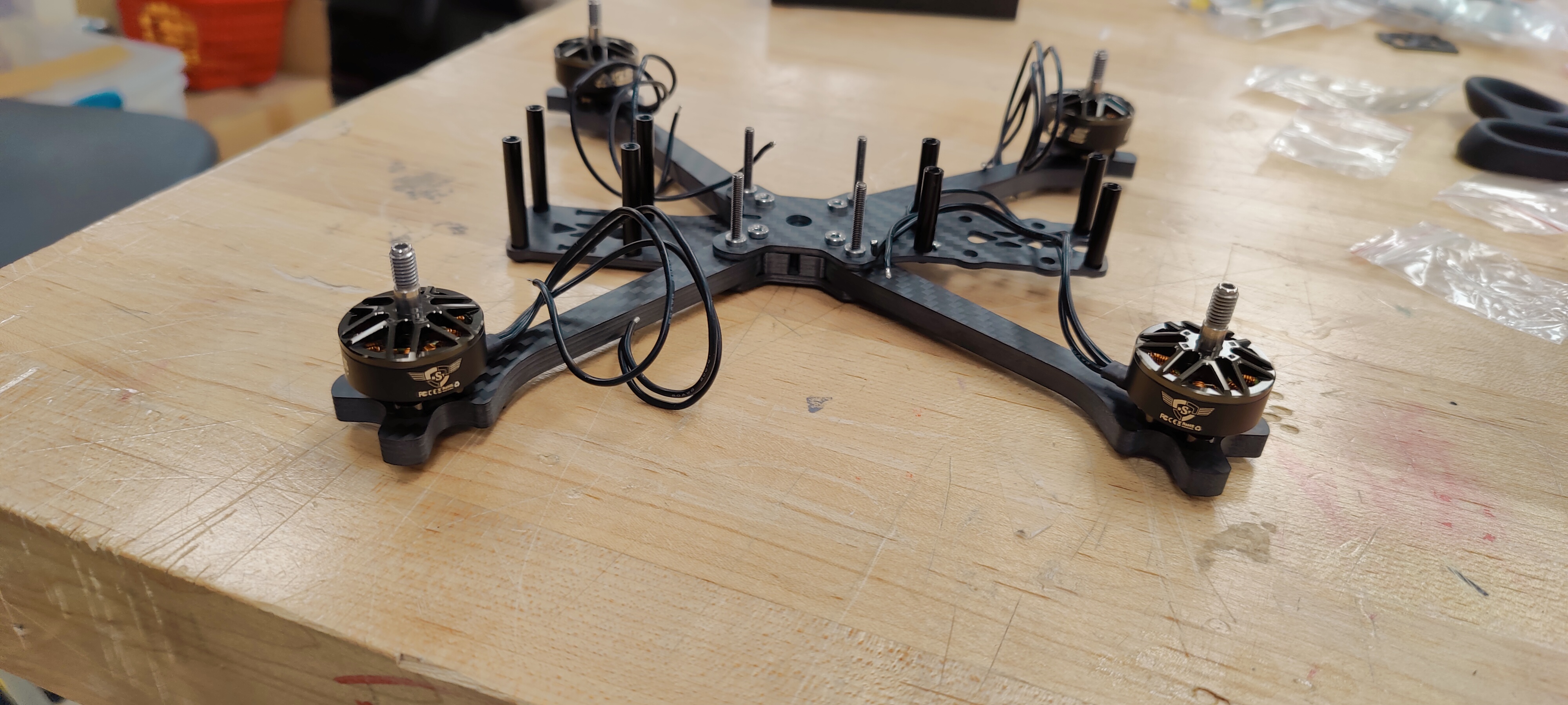
The frame with four motors mounted, before the electronics stack and propellers were installed.
My first pass through the system
I worked through soldering, BLDC motors, ESCs, flight-controller setup, LiPo power, propeller configuration, and Betaflight. Assembling the kit helped me connect those names to actual components, wiring, and configuration choices.
This phase was about becoming familiar with the drone system. It was the foundation for the custom work that came next, not a demonstration of autonomous landing.
The hardware did not stop here.
For the next phase, I brought in two teammates. We reused nearly all of the propulsion and electronics, designed a custom frame, and turned the hardware into a single-axis pivot test platform. The new material purchase was a $21.99 spool of PLA.
Phase 1 / Bill of materials
What I started with.
| Item | Quantity | Line cost |
|---|---|---|
| Quadcopter frame | 1 | $19.99 |
| Brushless DC motors | 4 | $39.96 |
| Electronic speed controllers | 4 | $31.96 |
| Betaflight-compatible flight controller | 1 | $27.99 |
| Power distribution hardware | 1 | $8.99 |
| Propeller set | 1 | $8.99 |
| 3S LiPo battery | 1 | $23.99 |
| RC transmitter + receiver | 1 | $49.99 |
| XT60 connectors and wiring | 1 set | $8.99 |
| Battery straps | 1 set | $3.99 |
| Fasteners and standoffs | 1 set | $5.99 |
| Heat-shrink / insulation | 1 set | $4.99 |
| Solder and assembly consumables | 1 | $3.50 |
| Phase 1 total | $239.32 | |
Across both phases
$261.31 in purchased materials.
$239.32 for the individual kit build + $21.99 for the team pivot rig. Reusing the first build made the second one possible without buying another hardware set.
The longer game
A side quest—with a direction.
I know this looks like another side quest. Trust me, it’s going to come together. While I keep working on rocketry, I’m building up what I know about propulsion, control, and testing here. The bigger goal is a self-landing system; the kit and the pivot rig are steps toward that.
Continue exploring.
← Back to Selected Builds